/prod01/channel_54/media/fit-website/site-assets/images/FT-Horiz_crimson-gold.png)
/prod01/channel_54/media/site-specific/researchfitedu/center-for-advanced-coatings/images/GettyImages-502074908.jpg)
Laser Laboratory
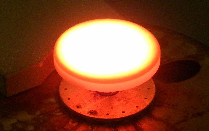
The High Heat Flux Test Laboratory is a state-of-the-art facility originally developed for testing ceramic thermal barrier coatings used in the turbine engine industry. Utilizing a 2 kW CO2 laser configured to TEM00, pryometer thermal sensors, various camera systems, a high pressure, high flow compressor, all controlled and monitored via a custom software application written in LabVIEW, materials are tested across a range of temperatures up to 1700 degrees Celsius, continuously monitoring and recording all data at the rate of 1 data sample per second (1Hz).
Important features: Noncontact with specimen, instantaneous heat flux or computer control of heat flux, computer controlled cooling, no contamination by container, and gaseous environments acceptable.
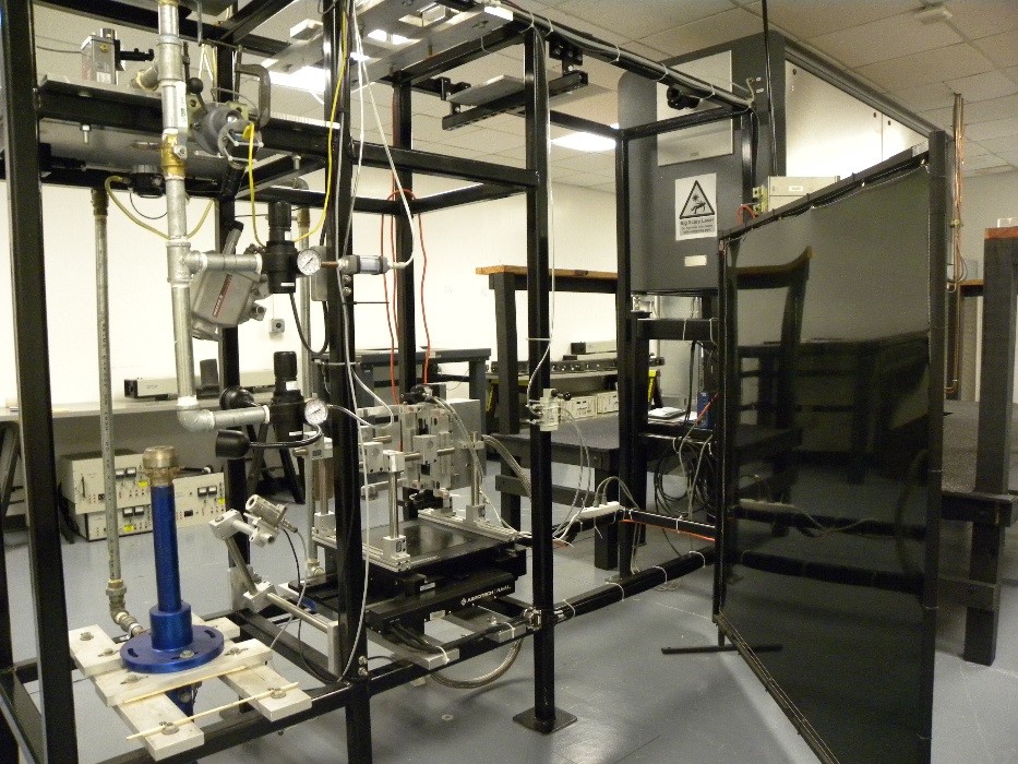
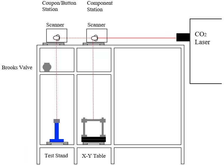
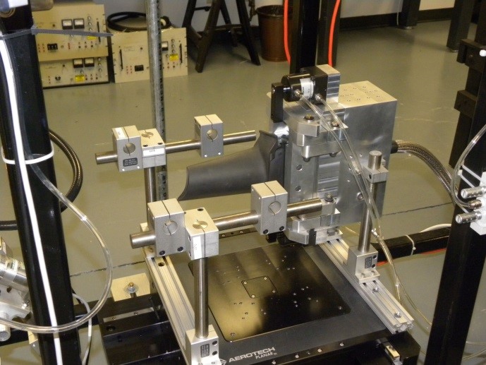
High Heat Flux Facility with Button and Component Work Stations
- Frame mounted CO2 laser (PRC Laser Model STS3300 configured to operate in the TEM00 mode at up to 2 kW) and a SCANLab scanner
- Button work station with cooling mount (on left)
- Component work station with blade cooling fixture (on right)
- Steel test frame and aluminum test stand
- Ircon Modline 3one-color pyrometer, operating at 7.92µ from 200 to 1800°C
- Optris 2ML ratio pyrometer, from 275 to 100°C
- Optrix IR camera and FLIR IR camera
- Two high speed air-jet at max speed ~100 m/s
- Brooks Mass Flow precision, computer controlled air valve operating at 225 PSI up to 2500 liters per minute flow rate
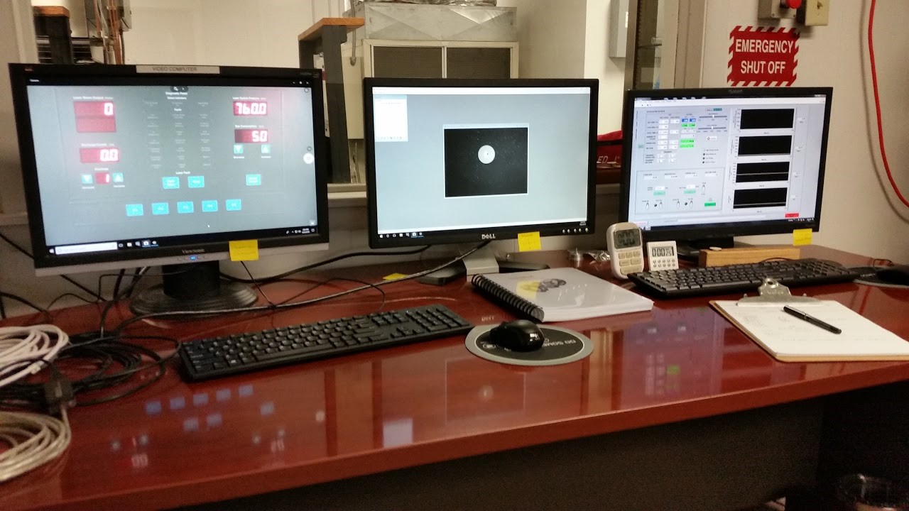
- PC Computer running the in-house proprietary laser rig control application.
- This software controls all functional elements of the test rig, collects and records the data from the pyrometers, laser, and cooling air, and provides safety protocols to prevent catastrophic failure of the test rig. The software allows two test modes: constant temperature control and nearly constant heat flux control.
- High resolution Ethernet camera to monitor the test sample
- HD webcams to monitor the test rig
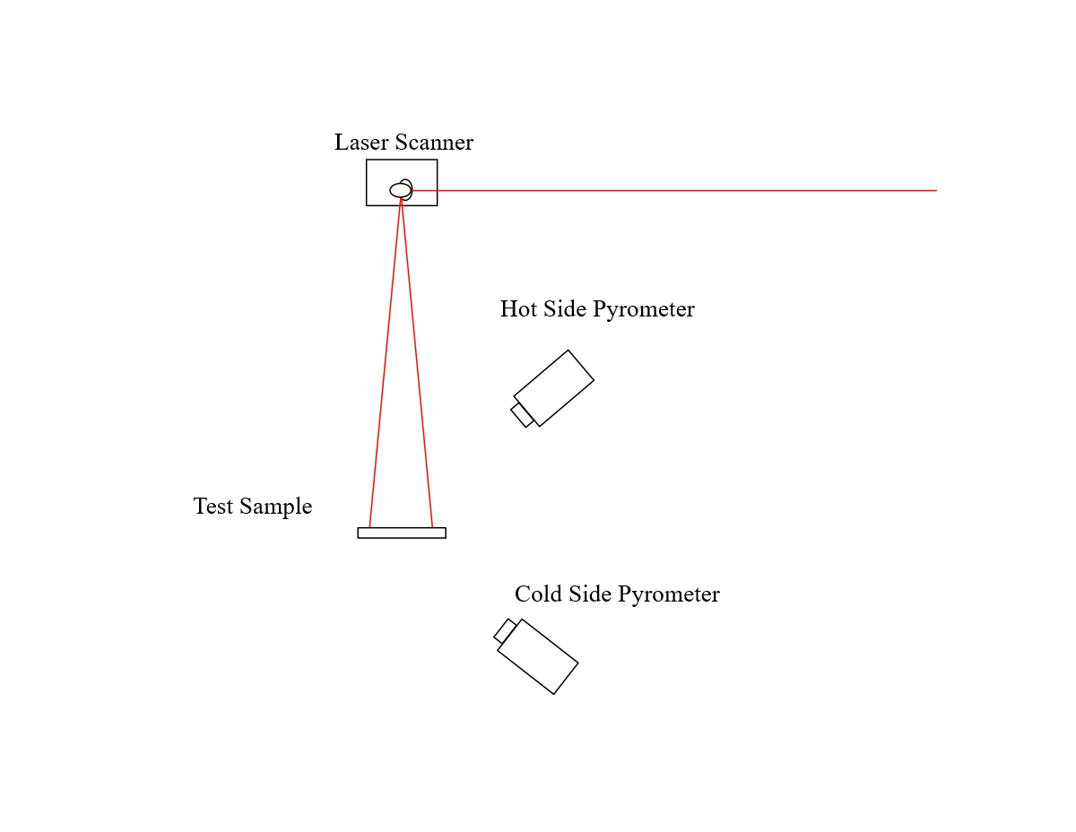
The raw, unfocused laser beam (5 mm FWHM) is emitted from the laser aperture and travels to the scanner, where it is directed down to either the coupon/button test sample mounted on the test stand or to the component test stations.
LabVIEW Software
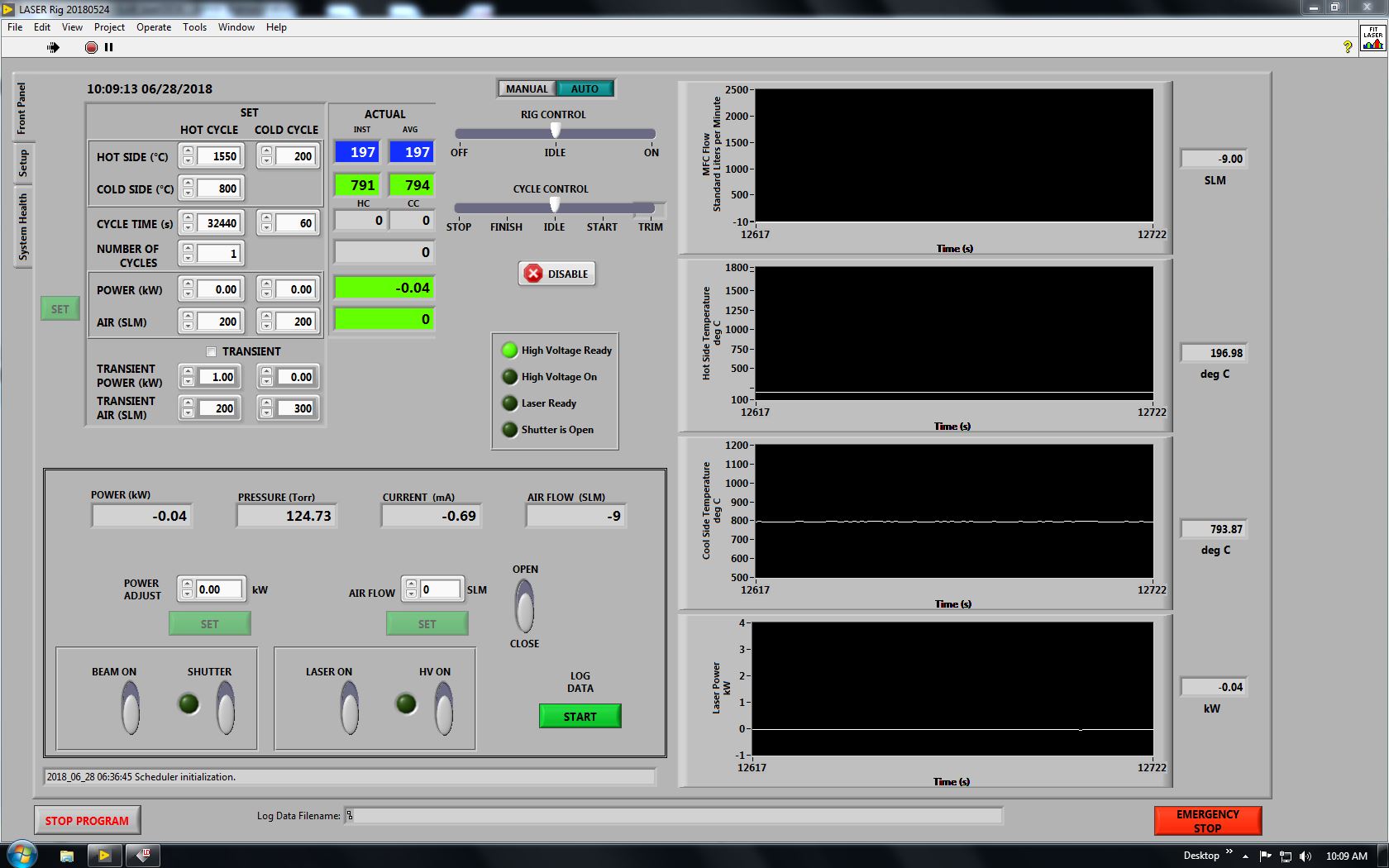
The LabVIEW application software controls and monitors all aspects of the laser test rig, including the laser, Brooks Mass Flow valve, and pryometers. The data from the pryometer, the laser, and the Brooks valve is recorded into a comma-separated-values (.csv) data files for thermal analysis. After failure, the samples are analyzed metallographically and compared with the thermal data. Camera feeds monitor the laser status and the test samples/components.
Laser Scanning Systems for Component Testing in the Second Work Station:
The scanning system enables complex geometries such as turbine blades to be tested in the high heat flux facility.
Important features: Ability to subject complex, three-dimensional components to high heat flux, results from the button specimens can be directly applied to components, video monitoring for failure identification, and data acquisition and control system.