Lab Overview
- Spacecraft proximity maneuver kinematics and dynamics testbed
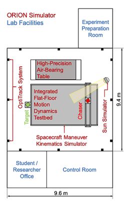
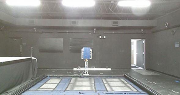
- Workspace: 9.4 m × 9.7 m × 2.7 m
- Maneuver Kinematics Simulator
- Integrated Flat-Floor Motion Dynamics
Testbed - High-Precision Air-Bearing Table
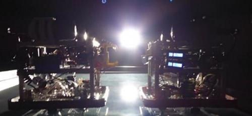
- Orbital lighting simulation
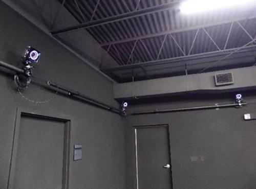
- Real-time object tracking using OptiTrack system
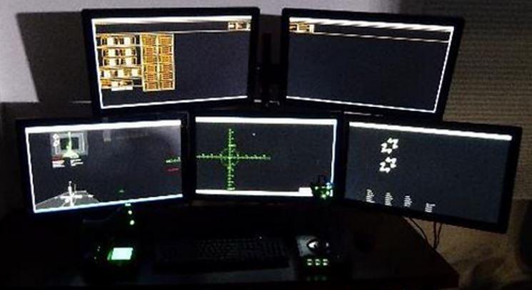
- Control Room with space dedicated to prototype system operators
- Hardware integration and storage spaces
- All lab components interconnected by WiFi
- Network ports for remote connectivity available
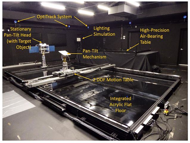
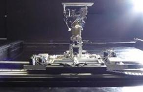
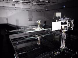
- Planar, gantry-based simulator for relative orbital dynamics between two spacecraft
- Combination of motion table and pan-tilt mechanisms enable simulation of 3D viewing conditions.
- Workspace: 5.5 m x 3.5 m
- Pan-tilt mechanisms for test articles of up to 20 kg, supplied with 120 V AC and Ethernet
- Pan-tilt heads can be removed to support other mechanisms, such as robotic manipulators
- Enables sensor testing, GNC law verification, teleoperation experiments, etc.
- Total 6 degrees of freedom
| Degree of Freedom | Motion Range | Max. Vol. | Max Accel. |
|---|---|---|---|
| Chaser X translation | 5.5m | 0.25 m/s | 1 m/s2 |
| Chaser Y translation | 3.5m | 0.25 m/s | 1 m/s2 |
|
Chaser pitch |
±90* | 60*/s | 60*/s2 |
| Chaser yaw | inf. | 60*/s | 60*/s2 |
| Target pitch | ±90* | 60*/s | 60*/s2 |
| Target yaw | inf. | 60*/s | 60*/s2 |
Two air-bearing motion dynamics testbeds enable experiments of spacecraft maneuver dynamics and contact dynamics.
Integrated Flat Floor
- 5.9 m x 3.6 m acrylic flat floor within the frames of the Maneuver Kinematics Simulator
- Enables coordinated use of gantry mechanism with
air-bearing vehicles for kinematics/dynamics experiments such as robotic capture of debris objects
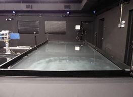
High-Precision Air-Bearing Table
- 3.6 m x 1.8 m tempered glass plate on optical bench with pneumatic vibration isolators
- Enables experiments in contact dynamics, spacecraft controls, formation flight, docking/capture, etc.
- Planar air-bearing vehicles (ABV) for formation flight and docking / capture experiments
- Propulsion: custom thrusters using compressed N2
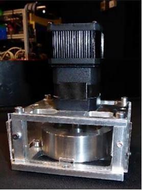
- Attitude control: Thrusters or custom reaction wheels
- On-board computer: Intel i5
- Endurance: ~20 minutes
- Aluminum frame allows easy attachment of capture tools, docking interfaces, sensors, robot manipulators, etc.
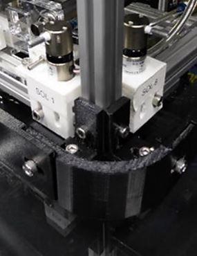
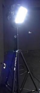
- Hilio D12 LED high-intensity light panel used to simulate orbital lighting conditions
- Light panel is daylight balanced
- Equivalent to 2000 W incandescent light
- Intensity sufficient to oversaturate dynamic range of cameras, produce stark light/shadow differences, and blind laser range finders.
- Lens inserts used to change the beam angle between 15° and 60°.
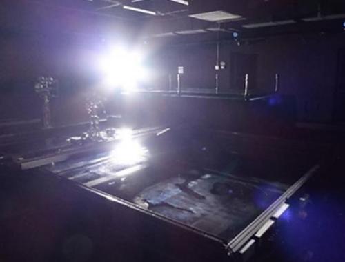
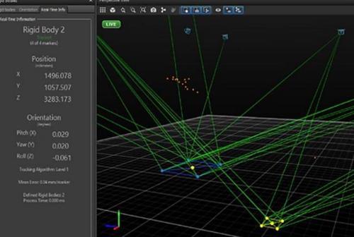
- 12-camera OptiTrack Prime 17W system tracks objects within the ORION Lab with sub-millimeter and sub-degree accuracy
- Objects are defined by four infrared reflectors
- Real-time streaming of tracking data on the lab network
- Used in closed-loop control of the Maneuver Kinematics Simulator
- For formation flight and docking experiments, OptiTrack can be used as stand-in for relative navigation sensors
- For sensor testing, the OptiTrack data serves as ground truth
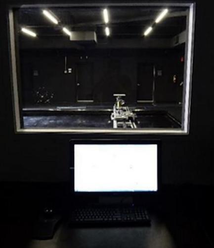
- ORION Control Room has a control station for the testbed and multiple workstations for equipment operators and test engineers
- Teleoperation console equipped with multiple input devices to support experiments in the teleoperation of ground, air, and space robots and vehicles.
- Operator at teleoperation console do not have direct sight of the testbed and all video and telemetry channels can feature artificial time delays.
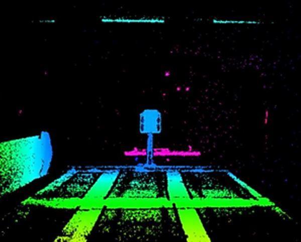
- Use of multiple swarm satellites equipped with 3D cameras (stereoscopic / time-of-flight) to produce point-cloud model of resident space object
- Point cloud will be processed to:
- Characterize target motion (tumbling axis and rates)
- Map geometry of target
- Identify surface features for capture, servicing, neutralization, etc.
- Capability enables swarms of small satellites to inspect, characterize, safely approach and engage non-cooperative resident space object
- Applications:
- On-orbit servicing
- Debris removal
- Inspection
- Protection and defense

 Give to Florida Tech